|
Earth Science Associates |
||||||||||
|
|||||||||||
|
Radiohalos |
|||||||||||
|
|
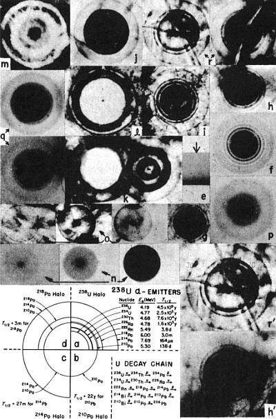
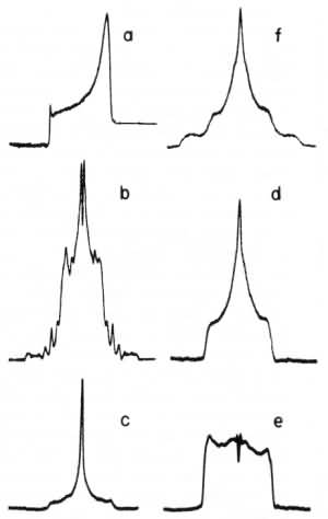
Science, vol. 184, pp. 62-66, April 5, 1974.Abstract. New photographic evidence, data on halo ring sizes, and x-ray fluorescence analyses provide unambiguous evidence that polonium halos exist as a separate and distinct class apart from uranium halos. Because of the short half-lives of the polonium isotopes involved, it is not clear how polonium halos may be explained on the basis of currently accepted cosmological models of Earth formation. I have examined some 105 or more radiohalos, mainly from Precambrian granites and pegmatites located in several continents. In addition to U and Th halos, originally studied (1, 2) for information on the constancy of the α-decay energy Eα and the decay constant λ, I have discussed X halos (2, 3), dwarf halos (3), and giant halos (4), and explained how these remain prime candidates for identifying unknown α-radioactivity and, not impossibly, unknown elements as well. I have also reported (5) on a class of halos which had been tentatively attributed (6, 7) to the α-decay of 210Po, 214Po, and 218Po. Earlier investigators (2, 7-10), possessing only a sparse collection of Po halos, at times confused them with U halos or invented spurious types such as "emanation" halos (2) or "actinium" halos (8) to account for them. (Figure 1, a to d, is a schematic comparison of U and Po halo types with ring radii drawn proportional to the respective ranges of α-particles in air.) To explain Po halos, Henderson (7) postulated a slow accumulation of Po isotopes (or their respective β-decay precursors) from U daughter product activity. I demonstrated that this secondary accumulation hypothesis was untenable and showed, using the ion microprobe (3), that Po halo radiocenters (or inclusions) exhibit anomalously high 206Pb/207Pb isotope ratios which are a necessary consequence of Po α-decay to 206Pb. Recently, these ion microprobe results have been questioned, Henderson's results misinterpreted, Po halos considered to be only U halos, and allusions made to the geological difficulties that Po halos would present if they were real (11) [see (12) for comments]. Admittedly, compared to ordinary Pb types, the Pb isotope ratios of Po halos are unusual, but new ion microprobe analyses have confirmed (13) my earlier results (3). It is also apparent that Po halos do pose contradictions to currently held views of Earth history. For example, there is first the problem of how isotopic separation of several Po isotopes [or their β-decay precursors (13)] could have occurred naturally. Second, a straightforward explanation of 218Po halos implies that the 1-μm radiocenters of very dark halos of this type initially contained as many as 5 × 10⁹ atoms (a concentration of more than 50 percent) of the isotope 218Po (half-life, 3 minutes), a problem that almost defies reason. A further necessary consequence, that such Po halos could have formed only if the host rocks underwent a rapid crystallization, renders exceedingly difficult, in my estimation, the prospect of explaining these halos by physical laws as presently understood. In brief, Po halos are an enigma, and their ring structure as well as other distinguishing characteristics need to be made abundantly clear. In order to ascertain the Eα corresponding to a specific halo radius, I have produced a new series of standard sizes against which halo radii may be compared without relying on estimates derived from ranges of α-particles in air. Standard sizes may be prepared by irradiation of halo-bearing mineral samples with 4He ions (4); the coloration bands thus produced show varying sizes (as measured from edge to coloration extinction) which are dependent on energy, total dose, and dose rate, the latter two factors not being accounted for in other comparative methods. I made more than 350 irradiations 1 to 104 seconds in duration using 4He ions with energies ranging from 1 to 15 Mev, on over 40 samples of biotite, fluorite, and cordierite (14). Selecting the band sizes which correspond to the energies of the 238U α-emitters (see Table 1) permits a direct comparison with new as well as previous (1, 9, 10, 15) U halo measurements in biotite, fluorite, and cordierite. Figure 1e shows a coloration band in biotite produced by 7.7-Mev 4He ions, and Fig. 2a shows a densitometer profile of Fig. 1e.
The coloration extinction boundary is poorly defined near threshold coloration; only a few very light bands in biotite could be reliably measured. Reproducible measurements were obtained in the plateau region (14), where variations in band size are minimal. Darker halos in biotite generally have slightly larger radii than lighter halos (3, 4). Also, reversal effects in some biotites immediately exterior to the terminus of a halo ring cause apparent diminution of the radius. Therefore, while there are differences between the sizes of medium coloration hands (Table 1, column 2) and the radii of U halos in biotite (Table 1, columns 8, 9, and 10) that could be interpreted in terms of an actual change in Eα and λ (16), such differences more likely arise from a combination of dose and reversal effects (15, 17), producing slightly diminished radii. Diminution of U halo radii may also result from attenuation of α-particles within the small but relatively dense zircon radiocenters. Even though slight differences between band sizes and U halo radii do exist in biotite, the idealized U halo ring structure (Fig. 1a) compares very well with an actual U halo in biotite (Fig. 1f). Biotite and fluorite are good halo detectors, but fluorite is superior because the halo rings exhibit more detail, often have smaller radiocenter diameters (< 1 μm), and have almost negligible size variations due to dose effects in the embryonic to normal stages of development. Figure 1g shows an embryonic U halo in fluorite with only the first two rings fully developed; the other rings are barely visible because, due to the inverse square effect, threshold coloration has not been reached. Figure 1h shows a U halo in fluorite in the normal stage of development, when nearly all the rings are visible. This halo closely approximates the idealized U halo in Fig. 1a. Under high magnification even separation of the 210Po and 222Rn rings may be seen. Figure 1i shows another U halo in fluorite, with a ring structure that is clearly visible but not adequate for accurate radius measurements. In Table 1, columns 4, 11, and 12, the fluorite band sizes agree very well with the U halo radii measured in this mineral by myself and Schilling (9). This suggests that the differences between U halo radii and band sizes in biotite are not due to a change in Eα However, experimental uncertainties in measuring U halo radii preclude establishing the constancy of λ to within 35 percent, and under certain assumptions U halos provide no information at all in this respect (16). While halos with point-like nuclei which show well-defined, normally developed rings (as in Fig. 1h) can be used to determine the Eα's of the radionuclides in the inclusion, there are pitfalls in ascertaining what constitutes a normally developed ring. In contrast to the easily recognizable U halos in fluorite in Fig. 1, g to i, the overexposed fluorite U halo in Fig. 1j shows a diminutive ghost inner ring, which could be mistaken for an actual 238U ring. Figure 1k shows two other partially reversed U halos, one of which shows the diminutive inner ring, while in the other all the inner rings are obliterated. The U halo in Fig. 1l is even more overexposed, and encroaching reversal effects have given rise to another ghost ring just inside the periphery. Figure 1m shows a still more overexposed U halo; in which second-stage reversal effects have produced spurious ghost rings that are unrelated to the terminal α-particle ranges. Since this association of the halos in Fig. 1, l and m, with U α-decay cannot be easily proved by ring structure analysis alone, I have utilized electron-induced x-ray fluorescence to confirm this identification. Figure 3a shows the prominent Ca x-ray lines of the fluorite matrix (the F lines are below detection threshold) along with some background Ag and Rh lines which are not from the sample, but are produced when back-scattered electrons strike a Ag-Rh alloy pole piece in the sample chamber. Figure 3b, the x-ray spectrum of a halo radiocenter typical of the halos in Fig. 1, l and m, clearly shows the x-ray lines due to U (as well as a small amount of Si) in addition to the matrix and background peaks. A more detailed analysis (18) reveals that the Uζ line masks a small amount of Pb probably generated by in situ U decay. The variety of U halos shown in Fig. 1, g to m, establishes two points: (i) only a thorough search will reveal the numerous variations in appearance of U halos, and (ii) unless such a search is made, the existence of halos originating with α-emitters other than 238U or 232Th could easily be overlooked. So far, three criteria have been used to establish the identity of U halos: (i) close resemblance of actual halos in biotile (Fig. 1f) and fluorite (Fig. 1h) to the idealized ring structure (Fig. 1a), (ii) identification of lines in x-ray fluorescence spectra, and (iii) agreement between U halo radii and equivalent band sizes (very good in fluorite and fair in biotite and cordierite). Using the third criterion (either band sizes or U halo radii) I can determine Eαfor a normally developed fluorite halo ring to within ± 0.1 Mev. For biotite halos, U halo radii may form a suitable standard for determining Eα for rings that show reversal or other effects characteristic of U halos in the same sample. If good U halos are not available, and if the halos with variant sizes show well-developed rings without reversal effects, then the band sizes form a suitable standard for Eα determination when coloration intensities of variant halos and band sizes are matched.
Therefore, if halos result from the α-decay of 210Po to 206Pb, their appearance should resemble the idealized schematic (Fig. 1b), and the light and dark halos of this type in biotite should exhibit radius variations consistent with the differences between lower and higher coloration band sizes (Table 1, columns 2, 3, 6, 14, and 15). Further, such halos, whether very light or very dark, should appear without any outer ring structure, as illustrated in Fig. 1n. Compare also the densitometer profiles of the halo negatives of Fig. 1f (the U halo) and Fig. 1n shown in Fig. 2b and Fig. 2, c to e, respectively. Fig. 1o shows three similar halos in fluorite; here, irrespective of coloration differences, the halo radii are the same and correspond to the Eα of 210Po (Table 1, columns 4, 6, and 20). Accordingly, the halos in Fig. 1, n and o, are designated 210Po halos. (Actually I should emphasize that since not all biotites exhibit the same coloration responses, the radius measurements in Table 1 are strictly valid only for the particular micas I used. I did try to illustrate a range of responses by utilizing four different biotites for the U halo and the three Po halo types.) By analogy, the moderately developed biotite halo in Fig. 1p shows a marked resemblance to the idealized halo that would form from the sequential α-decay of 214Po and 210Po (see Fig. 1c). Table 1, columns 2, 3, 6, 7, 16, and 17, shows the correspondence of the radii with band sizes. The prominent unmistakable feature of the 214Po halo is the broad annulus separating the inner and outer rings [see the densitometer profile of Fig. 1p shown in Fig. 2f and figures 7 to 9 in (6)]. With respect to comments in (11) it should be noted that the 214Po halo can easily be distinguished from a U halo. The last correspondence to be established is the resemblance of the two three-ring halos in biotite (Fig. 1q) and two similar halos in fluorite (Fig. 1r) to the idealized 218Po halo (Fig. 1d) showing the ring structure from the sequential α-decay of 218Po 214Po, and 210Po. In biotite such halos may appear very light to very dark with radii correspondingly slightly lower and higher (excluding reversal effects) than those measured for medium coloration bands (compare Table 1, columns 2, 3, 18, and 19). Cursory examination of inferior specimens of this halo type could lead to confusion with the U halo, especially in biotite, where ring sizes vary slightly because of dose and other effects. However, good specimens of this type are easily distinguished from U halos, even in biotite. In fluorite, where the ring detail is better, a most important difference between 238U and 218Po halos is delineated, that is, the presence of the 222Rn ring in the U halo (Fig. 1a) in contrast to its absence in the 218Po halo (Fig. 1d). For example, note the slightly wider annulus (3.9 μm) between the 210Po and 218Po rings of the 218Po halo compared to the equivalent annulus (3.0 μm) in the 238U halo (Fig. 1, a, d, h, h', r, and r'). This is evidence that the 218Po halo indeed initiated with 218Po rather than with 222Rn or any other α-decay precursor in the U chain. As further proof, Table 1 (columns 4, 11, 12, and 21 shows that the 218Po halo radii agree very well with equivalent band sizes and U halo radii in this mineral. Additional Po halo types also exist (3) but are quite rare. [As yet I have found no halos at all in meteorites or lunar rocks (19)].
The preceding discussion has shown that Po halos can be positively identified by ring structure studies alone. That x-ray fluorescence analyses also provide quite convincing evidence is seen in Fig. 3c, where I show for the first time the x-ray spectra of a Po halo radiocenter (specifically, a 218Po halo). Comparison of Fig. 3, b and c, reveals that the Pb in the Po halo radiocenter in fluorite did not arise from in situ decay of U. [Longer runs have shown small amounts as Se as well as U in some Po halo radiocenters (18).] On the other hand, the presence of Pb is to be expected in a 218Po halo radiocenter because the decay product is 206Pb. That the parent nuclide was 218Po and not a β-decaying isomer precursor (13, 20) follows from half-life considerations of the U halo U/Pb ratio (> 10); the proposed isomer, if formed at nucleosynthesis, should now be detectable in Po halo radiocenters. No trace of this isomer has yet been found, and I thus view the isomer hypothesis as untenable. The x-ray data in Fig. 3c are unambiguous and should remove any doubt that previously reported 206Pb/207Pb mass ratios (3, 13) actually are Pb isotope ratios, and in fact represent a new type of Pb derived specifically from Po α-decay. In summary, the combined results of ring structure studies, mass spectrometric analyses, and electron induced x-ray fluorescence present a compelling case for the independent existence of Po halos. The question is, can they be explained by presently accepted cosmological and geological concepts relating to the origin and development of Earth?
References and Notes
2 July 1973; revised 26 December 1973 |
|
||||||||
|
|
|||||||||||
|
|||||||||||
|
Earth Science Associates
|
|||||||||||